Introduction: The appearance of frequency converters brings innovations for industrial automation control and motor energy conservation. In industrial production, inverters are almost inseparable. Even in daily life, elevators and inverter air conditioners have become indispensable parts. Inverters have begun to infiltrate into every corner of production and life. However, the inverter also brings many unprecedented difficulties, among which the damaged motor is one of the most typical phenomena. Source: Hangzhou Zhuoyi Xin Automation Technology Co., Ltd.
Ambient Temperature: 40
Special High Voltage Generator
Special High Voltage Generator Double Bearing Generator,Special High Voltage Generator,Blue Brushless Generator EvoTec Power Generation Co., Ltd , https://www.evotecgen.com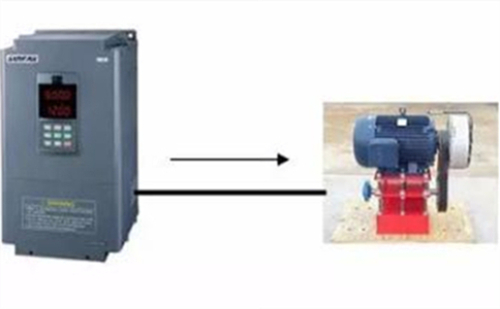
Many people have found that the inverter damages the motor. For example, in a pump plant, in the past two years, his users frequently reported that the pump was damaged during the warranty period. In the past, the product quality of this water pump plant was very reliable. After investigation, it was found that these damaged pumps were driven by frequency converters.
Although the phenomenon that the inverter damages the motor is more and more concerned by people, the mechanism that causes this phenomenon is still unclear, and even less knows how to prevent it. The purpose of this article is to solve these puzzles.
First, the inverter damage to the motor
Inverter damage to the motor includes two aspects: stator winding damage and bearing damage, as shown in Figure 1. This damage usually occurs within a few weeks to ten months, the specific time and the brand of the inverter, the brand of the motor, the power of the motor, the carrier frequency of the inverter, the cable length between the inverter and the motor, the ambient temperature, etc. There are many factors involved. The early accidental damage to the motor brought huge economic losses to the company's production. This loss is not only the cost of motor maintenance and replacement, but also the economic loss caused by unexpected shutdown. Therefore, when using the inverter to drive the motor, it must pay enough attention to the problem of motor damage.
Second, the difference between frequency converter drive and power frequency drive
To understand the mechanism of the power frequency motor damage more easily under the drive conditions of the drive, first understand the difference between the drive voltage of the drive motor and the power frequency voltage. Then understand how this difference affects the motor.
The basic structure of the inverter includes two parts: the rectifier circuit and the inverter circuit. The rectifier circuit is a DC voltage output circuit composed of an ordinary diode and a filter capacitor, and the inverter circuit converts the DC voltage into a pulse width modulated voltage waveform (PWM voltage). Therefore, the voltage waveform of the inverter-driven motor is a pulse waveform in which the pulse width changes, not a sine wave voltage waveform. Driving a motor with a pulsed voltage is the root cause of the damage to the motor.
Third, the inverter damage motor stator winding mechanism
When the pulse voltage is transmitted over the cable, if the impedance of the cable does not match the impedance of the load, a reflection occurs at the load end. As a result of the reflection, the incident wave and the reflected wave are superimposed to form a higher voltage, and its amplitude can be up to twice the DC bus voltage, approximately three times the input voltage of the inverter. Excessive spike voltage is added to the motor. Stator coils cause voltage surges on the coils, and frequent overvoltage surges can cause premature failure of the motor.
After the inverter-driven motor is impacted by a spike voltage, its actual lifetime is related to many factors, including temperature, pollution, vibration, voltage, carrier frequency, coil insulation process, and other factors.
The higher the carrier frequency of the inverter, the closer the output current waveform is to the sine wave, which will reduce the operating temperature of the motor and extend the life of the insulation. However, a higher carrier frequency means more spikes per second and more impact on the motor.
The higher the temperature of the motor, the shorter the insulation life. When the temperature rises to 75 degrees, the life of the motor is only 50%. Inverter-driven motors, because the PWM voltage contains more high frequency components, the motor temperature will be much higher than the power frequency voltage drive.
Fourth, the inverter damage motor bearing mechanism
The reason that the inverter damages the motor bearing is that there is current flowing through the bearing, and this current is intermittently connected. An intermittently connected circuit generates an arc and the arc burns the bearing.
There are two main causes of current flowing in the bearings of AC motors:
First, the induced voltage generated by the unbalanced internal electromagnetic field;
Second, stray capacitance causes high-frequency current paths.
The magnetic field inside the ideal AC induction motor is symmetrical. When the currents of the three-phase windings are equal and the phase difference is 120 ,, no voltage is induced on the shaft of the motor. When the PWM voltage output from the inverter causes the magnetic field inside the motor to be asymmetric, it will induce voltage on the shaft. The voltage amplitude is between 10~30V, which is related to the driving voltage. The higher the driving voltage, the higher the voltage on the shaft. high. When the value of this voltage exceeds the dielectric strength of the lubricating oil in the bearing, a current path is formed. During the rotation of the shaft, at some point, the insulation of the lubricant interrupts the current. This process is similar to the on-off process of a mechanical switch, in which arcs are generated and the surfaces of the shafts, balls, and bowls are ablated, forming pits. If there is no external vibration, the small pits will not produce excessive effects, but if there is external vibration, grooves will be generated, which has a great impact on the operation of the motor.
In addition, experiments have shown that the voltage on the shaft is also related to the fundamental frequency of the inverter output voltage. The lower the fundamental frequency, the higher the voltage on the shaft and the more serious the bearing damage.
In the early stage of the motor operation, when the lubricant temperature is low, the current amplitude is 5-200mA. Such a small current will not cause any damage to the bearing. However, when the motor is running for a period of time, the peak current will reach 5-10A as the temperature of the lubricating oil increases, which will cause arcing and form small pits on the surface of the bearing component.
Fifth, the protection of motor stator windings
When the length of the cable exceeds 30 meters, modern frequency converters will inevitably produce spike voltage at the motor end, shortening the life of the motor. To prevent damage to the motor, there are two ideas. One is to use a motor with a higher insulation resistance of the winding (commonly referred to as a variable-frequency motor), and the other is to take measures to reduce the peak voltage. The former measures are suitable for new projects, and the latter measure is suitable for retrofitting existing motors.
At present, there are four commonly used motor protection methods:
1) Install a reactor at the output of the inverter: this measure is most commonly used, but it should be noted that this method has a certain effect on shorter cables (below 30 meters), but sometimes the effect is not ideal, as shown in Figure 6 (c) ) as shown.
2) Install dv/dt filter at the output of the inverter: This measure is applicable to occasions where the cable length is less than 300 meters, the price is slightly higher than the reactor, but the effect has been significantly improved, as shown in Figure 6 (d) .
3) Install a sine wave filter at the output of the inverter: This measure is ideal. Because here, the PWM pulse voltage is changed to a sine wave voltage, and the motor operates under the same conditions as the power frequency voltage, and the problem of the spike voltage is completely solved (the cable is longer and there is no spike voltage). .
4) Install the peak voltage absorber at the position of the cable and motor interface: The disadvantage of the previous measures is that when the power of the motor is large, the size and weight of the reactor or filter are large, and the price is high. In addition, the reactor is Both the filter and the filter will cause a certain voltage drop and affect the output torque of the motor. The use of a frequency converter peak voltage absorber can overcome these disadvantages.
Evotec High Voltage Generator including Double Bearing Generator,Special High Voltage Generator,Blue Brushless Generator etc.
The specific technical features are listed below:
Speed: 1500rpm or 1800rpm
Frequency: 50 Hz or 60Hz
Number of Poles: 4
Power: up to 3500KVA
Voltage: 110V-690V,High Voltage:3.3KV-13.8KV
Insulation: class H
Power Factor: 0.8
Voltage Regulation Rate: ±0.5%
Altitude: 1000M
Temperature Rise Class: class H
Overload:10% for 1 hour in every 12 hours
Degree of Protection: IP21 (IP23, IP44, IP54 on request)
Special Features:
