For simple planar 2D contour parts: Manual programming is generally used; For the processing of upper and lower profiled ruled surfaces: Simple parts can be manually programmed, and complex parts can be graphically assisted with programming and computer-aided programming. 1. Basic process problems in CNC wire cutting (1) Setting of workpiece coordinate system and workpiece origin 1) Several workpieces can be installed at different positions on the machine table. Several workpiece coordinate systems need to be created. 2) The machine tool generally provides six workpiece coordinate systems, which are designated by G54-G59. 3) The origin of the workpiece should be selected to facilitate measurement or touch the wire, and at the same time it is easy to program and calculate. a) Machining punches b) Machining dies Fig. 1 Sketch of wire radius compensation (2) Selection of process parameters 1) Process parameters: refers to processing conditions, including: discharge pulse frequency and pulse width, current size, discharge gap and other parameters, these parameters and the workpiece material and its heat treatment status, workpiece thickness, processing accuracy, electrode wire (molybdenum wire) The diameter is relevant. 2) CNC wire-cutting machine tools generally provide a database of process parameters for processing program calls. 3) The process parameter database can be modified according to the cutting material and thickness. (3) Correct selection of threading holes, infeed lines and exit lines 1) The threading hole is a technological hole processed on the workpiece by other processing methods (such as drilling, EDM) before wire cutting. 2) The threading hole is the starting point of the movement of the molybdenum wire relative to the workpiece and is also the starting point of program execution. 3) The position of the threading hole: It should be selected in a position that is easy to find and easy to check during processing. 4) The position of the threading hole should be set on the workpiece. 5) The same applies to the selection of the infeed line and the exit line. (4) Establishment of wire radius compensation 1) Calculation method of radius compensation value: radius compensation value== molybdenum wire radius + discharge gap That is: D = wire radius + δ (δ is the discharge gap) 2) The establishment and cancellation of wire radius compensation is exactly the same as the compensation process in CNC milling. 3) The establishment and cancellation of wire radius compensation must use G01 linear interpolation instruction, and must be completed in the cutting process (infeed line) and the cutting process (retraction line), as shown in Figure 2. Figure 2 Creation and Cancellation of Wire Radius Compensation (G41) (5) Taper processing conditions 1) First you must enter the following parameters: 1 The distance S from the center of the guide wheel to the table surface. Fig. 3 Taper machining condition parameters 2) Taper machining establishment and exit Fig. 4 Taper cutting machining range and machining error analysis example 1 The process of establishing and exiting taper machining is shown in Figure 4: Taper machining (G51 or G52) is established, and taper processing is exited (G50) 2 The block must be a G01 linear interpolation block, which is completed in the infeed line and the retract line. 3 As shown in Figure 5a. The program surface in the figure is the lower surface of the workpiece to be machined, which coincides with the work surface. 4 Taper machining is established by establishing the yawing wire from the starting point of the taper machining linear interpolation block, and the wire yawing to the specified taper value at the end of the block, as shown in Fig. a. 5 Taper machining exit is from the starting point of the taper machining linear interpolation program starting from the yawing electrode wire, and the electrode wire swing back to 0° (vertical state) at the end of the program segment, as shown in Figure b. Fig. 5 Taper machining establishment and exit 3) Analysis of Taper Cutting Processing Range and Processing Error 1 Taper cutting processing range: ±6°/50mm (the machine cutting range of different machine taper is generally not the same). This value is only suitable for smooth-connected graphics. For the profile with non-smooth connection, because the edge angle is a composite angle that intersects both sides, the value is larger than the taper angle on the surface. Therefore, when the taper angle on the surface is 6o, the taper angle on the edge will be greater than 6°. Cutting. For example, when cutting a square pyramid with a taper of 6°, the taper angle on the rib is 8.792°, which has exceeded the cutting range of ±6° and cannot be cut. As shown in Figure 6. 2 Taper cutting machining error. a. Quick-cut wire cutting machine is a molybdenum wire that supports high-speed operation with a guide pulley. When taper processing is performed, the support tangent point will change slightly with the formation of taper. Therefore, it will inevitably bring about cutting errors. a) Errors due to tangential changes in the U direction. b) When the molybdenum wire in the V direction is deflected, the molybdenum wire is affected by the yawing tensile force and tends to slip along the guide pulley. Figure 6 Taper cutting error b. As the U-axis moves, the molybdenum wire is affected by the yawing tensile force, which will produce different slip trends in the guide wheel groove, and produce different errors in the V direction; this error is not easy to make quantitative calculations and can only be qualitative analysis. c. Quick taper cutting error is inevitably caused by a change in the tangent point of the guide wheel. Therefore, in the taper cutting, in order to improve the cutting accuracy, it is possible to feed in the direction of the ridge 45°, or to place the workpiece at an angle, so that the error formed by the change of the tangent point of the guide wheel cancels out in the dimension direction.
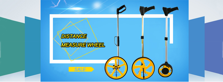
Measuring Wheel is also known as measure wheel.There are two types, mechanical and digital display measuring wheel. It is designed for outdoor distance measurement. It can be for a variety of ground conditions, including hills, meadows, and rugged construction sites and so on.
Features:
6.It is easy to use,great for real estate pros,appraisers,surveyors,law enforcement,facility engineers,flooring specialists,insurance agents,adjusters,decorators,painters,roofers.
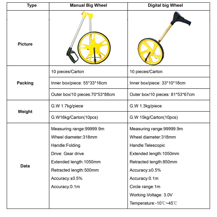
Distance Measuring Wheel specification:
Distance Measuring Wheel Distance Measuring Wheel,Measuring Wheel,Rolling Distance Measuring Wheel,Wheel Measuring Tool Hebei Long Zhuo Trade Co., Ltd. , https://www.hblongzhuo.com

2 The distance W from the table top to the center of the lower guide wheel.
3 workpiece thickness H. As shown in Figure 3. 


1. Accurate
2. Flexible and durable
3. Easy to operate
4. Light weight and easy to convenient
5. OEM is welcome

