Industrial aluminium profile,Industrial Aluminum Profiles,Aluminium railing profiles,T Slot Aluminum Extrusion Profiles,Solar Panel Aluminium Profiles,Heat Sink Aluminum Extrusion GUANGDONG YONGLONG ALUMINUM CO.,LTD , https://www.yonglongaluminium.com
In industrial and domestic settings, various substances such as gases, liquids, or steam are transported through pipelines. These fluids often have differing properties, which significantly affect their flow rates. Flow meters and flow transmitters play crucial roles in industries by measuring the flow of gases and liquids within pipelines. Flow transmitters are essentially more advanced versions of flow meters. While flow meters primarily monitor fluid flow, flow transmitters not only measure but also control fluid movement by detecting both input and output flows. These devices are equipped with electronic circuits that generate electrical signals ranging from 4 to 20 mA or 1 to 5V. Both instruments require calibration during installation and throughout their operational life. Renowned manufacturers like Rosemount and Foxboro provide high-quality flow transmitters, each with unique calibration procedures, although the fundamental steps remain consistent. This post explores different methods for calibrating flow transmitters.
### Calibration Process Based on Transmitter Type
Today, three primary types of flow transmitters are utilized: differential pressure transmitters, magnetic flow transmitters, and vortex flow transmitters. These types necessitate slightly intricate calibration processes, typically employing a master meter.
A master meter serves as a standardized, calibrated transmitter operating under optimal conditions and specifications. It acts as a reference point for calibrating active transmitters. The master meter used must adhere to international or national standards and be compatible with the fluid being tested.
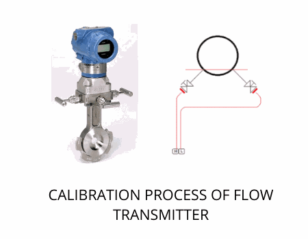
#### Calibration of Differential Pressure Transmitters:
Despite its name suggesting a focus on differential pressure, this type of transmitter actually measures flow fluctuations directly. Consequently, differential pressure (DP) transmitters are employed for flow measurement.
**Note:** The flow rate corresponds to the square root of the pressure drop. Thus, flow rate readings can be derived by squaring the recorded differential pressure values.
The calibration procedure for differential pressure transmitters is outlined below:
1. Connect the operating DP transmitter and the master meter or standard calibrator in series. Operate both devices simultaneously on the same pipeline under identical pressure conditions.
2. Perform calibrations at five checkpoints, marking these points as 10%, 30%, 50%, 70%, and 90% of the span.
3. Record inputs at each checkpoint for both the standard and operating transmitters.
4. Compare the readings of both devices at each checkpoint. Any discrepancy indicates a correction factor.
5. Adjust the parameters of the operating DP transmitter until the correction factor reaches zero. Repeat this process for all five checkpoints. Once all correction factors equal zero, the device is fully calibrated. Additionally, hysteresis must be verified since electronic devices might exhibit fluctuating readings for the same checkpoint.
6. Obtain the output value of the differential pressure at each point and square these values to determine flow rates. Cross-reference these final flow rates with the original manufacturer specifications provided in the manual.
#### Calibration of Magnetic Flow Transmitters:
Magnetic flow transmitters utilize a liquid as a conductor, causing the potential to vary with fluid velocity changes.
1. Calibration of the magnetic flow transmitter is conducted using a standard calibrator acting as a master meter.
2. The calibration involves a five-point check process.
3. Compute the input signal using the formula: Input Signal = Upper Range x Calibration Factor x Phase Band Factor.
4. Document output values at five distinct test points and calculate deviations and accuracy:
- Deviation = Theoretical Value - Actual Value
- Accuracy = (Deviation / Span) x 100
5. Align the accuracy with the manufacturer's specifications and adjust readings until the deviation equals zero.
#### Calibration of Vortex Flow Transmitters:
Vortex flow transmitters operate based on vortex shedding frequency. Calibration involves comparing the input pulse signal and output vortex flow frequency with a calibrator functioning as a master calibrator. Follow these steps to perform vortex flow calibration:
1. Calculate the vortex shedding frequency using the formula: Vortex Shedding Frequency = Reference Factor x Conversion Factor x (Upper Range Value in US Gallons / Time).
2. After calculating the vortex shedding frequency, set the span jumpers at five checkpoints. Connect a frequency generator to the input terminal of the transmitter and link the calibrator's output in series with the transmitter.
3. Adjust the fine span and proceed with the following steps:
- Set the frequency generator at the upper range value and adjust the fine span screw until reaching 100%. Then, calibrate the zero output value.
- Disconnect the frequency generator and attach the signal lead. Adjust the zero value to the lower range value.
- Fine-tune the zero setting until the input and output align.
- Execute this process for each of the five checkpoints to finalize the calibration.
When working with Rosemount flow transmitters, Foxboro flow meters, and similar devices, follow the manufacturer's guidelines for calibration. Expert assistance is essential for proper calibration. Therefore, consider partnering with companies like The Transmitter Shop, which specializes in providing factory-new, surplus, and reconditioned transmitters from Rosemount and Foxboro. They also offer services related to flow, temperature, and pressure measurements.
For further reading, explore topics such as calibrating pressure gauges, understanding reconditioned transmitters, and selecting appropriate pressure sensors.
---
This detailed guide aims to simplify the complexities involved in calibrating flow transmitters, ensuring precise measurements and optimal performance in various industrial applications.