Creative Autumn and Winter Warm kennels and cushions and Pet Clothing and grooming tools Cats and kennels Shenzhen Ananda Technology Co.,LTD , https://www.carmitek.com
First, the three-phase power supply common fault analysis Most of our power supply uses three-phase four-wire power supply. The following figure shows the schematic diagram of three-phase four-wire system. It can be seen from the figure that this kind of power supply can provide two different voltages—line voltage (380V) and phase voltage (220V), which can meet different needs of users. The ideal state of three-phase four-wire power supply is three-phase load balancing. At this time, the neutral current is zero. From the theoretical analysis, the neutral line at this time is optional, and it does not affect the normal operation of the equipment. But in reality, the three-phase balance is only relative, and the imbalance is absolute. Therefore, the middle line in practical applications is necessary, so as to ensure the stable output of each phase voltage. With the development of the economy, the use of electrical appliances has increased substantially, the probability of single-phase short-circuiting has inevitably increased, and zero-crossing voltage problems caused by single-phase short circuits and transient short circuits have become commonplace. Here we analyze some of the common faults and provide directions for the design of the power supply system of the power equipment so that the power supply system can operate stably and reliably. 

The open circuit of the transmission line is in the actual environment of the electricity environment, and the neutral line is often disconnected due to improper installation of the line or improper installation of the fuses and switches. If the neutral line breaks, the neutral point potential of the three-phase load will shift. The neutral point potential displacement directly leads to the unbalance of the output voltage of each phase, and the too high phase voltage will cause the device to overvoltage and directly burn, while the phase of the low phase voltage may damage the device due to the voltage drop and current increase. Because the calculation of the three-phase electric voltage is very complicated, due to the introduction of the load vector, the final detailed calculation formula is also very difficult to understand. The following is a simple way to explain the effect of the neutral short circuit on the line voltage. 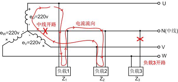
In addition to power lines, open circuit power equipment in the equipment is prone to failure, and equipment power input and socket failures may damage the equipment. Because most occasions use three-phase four-wire power supply, and three-phase four-wire power supply also has a more special application, and when using three-phase four-wire full-wave rectification, as long as any one phase of electrical equipment can be normal Operation. 
Second, three-phase power supply improvement measures Because there are more restrictions in practical applications, it is impossible to avoid the occurrence of many power failures, but we can reduce the probability of equipment damage through some means to improve product reliability. The specific improvement measures are as follows:
Single-phase short-circuit fault improvement measures This fault can properly improve the impact resistance of the input end of the power supply. Generally, it needs to resist the impact of 335VAC. This protects the post-circuit from damage due to overvoltage during transient short-circuits. In order to reduce the voltage increase caused by zero-floating, the cross-sectional area of ​​the zero line can be properly increased to reduce the zero drift, to reduce the voltage increase of the other two phases.
Open circuit improvement measures for the central line of the transmission line From the fault analysis we can see that the open circuit of the neutral line is mainly a current loop that affects the phase voltage, so that the current does not return to the neutral point. The loop can only be formed by two phase lines, which increases the risk of overvoltage in the equipment. In order to provide a reliable current loop for the phase voltage, the three-phase three-six-wire power supply mode can be adopted in the wiring, and the three-phase three-zero work independently. The disadvantage of this wiring is to increase the zero line investment and line loss, but this can effectively suppress zero drift and reduce the mutual influence of each phase voltage.
The open circuit improvement measures for equipment power supply neutral line The general equipment adopts a three-phase four-wire full-wave rectification circuit, mainly considering the redundant design of its power supply, as long as the three-phase power any one phase electric equipment can work normally. However, once the device is not connected to the neutral line, the voltage of the rectifier circuit will rise sharply. To solve this problem, it is necessary to cut off the post-stage circuit when the voltage increases, thereby protecting the post-stage circuit from being damaged. However, it is necessary to ensure that the detection control circuit is stable in power supply during design.
Third, from the root to solve the power system power failure With the development of society, the power of the power equipment is gradually increased, while the quality of various equipment is also uneven. These devices not only cause great interference to the power grid, but also have a greater risk of short circuit. There are many incentives for power failure and it is impossible to completely avoid its occurrence. But once the failure occurs, we need to feedback and handle it in a timely manner. At this point, there is a need for a power detection device to detect the power grid in real time, and take necessary measures when the fault occurs to avoid causing greater losses. 
PD2IHBxxD-10W Features:
Conversion efficiency up to 83%;
Input voltage: 56 ~ 700VDC;
Output voltage: 5V, 12V, 15V, 24V;
Working temperature: -40°C~+85°C;
Enable (EN) control function;
Isolation voltage: 4000VAC;
Sustained short circuit and self-recovery, with over-temperature protection function;
Single-phase circuit application features: Single-phase circuit is simple, can adapt to the mains voltage fluctuations.
Three-phase three-wire application features: Suitable for occasions without a midline, any one phase line open, the power supply can continue to work.
Three-phase four-wire application features: The biggest advantage of this circuit is that three-phase redundant power supply, the circuit can still work stably when there is no phase.
Foreword
In the power system, equipment failure caused by unreasonable power supply design occurs from time to time, so higher requirements are placed on the reliability and stability of the power supply circuit. The traditional power supply circuits mostly use power frequency transformers and a post-buck converter circuit. Due to the frequent occurrence of three-phase power supply failure in recent years, the power supply system can still supply power to the power detection equipment in a stable and reliable manner in order to solve the problem of failure of the three-phase power supply. Many power supply manufacturers have introduced high-frequency switching power supplies dedicated to electricity. This power supply has many advantages: safety, reliability, small size, light weight, high overall efficiency, and low noise. It is very suitable for the application of power grid equipment. Many large-scale devices are currently used. Manufacturers have begun to use in batches.
Figure 1 three-phase voltage diagram
Single-phase short-circuit faults In many cases, in order to take power conveniently, three-phase phase voltages are used directly. Including many current rural power grid designs, the three phases of the three-phase power are equally distributed to three groups of users, thereby eliminating the need for three-phase transformers. Although this kind of power supply method saves some equipment investment, it brings a great deal of hidden danger to the user's power equipment. In practical applications, the probability of occurrence of a single-phase short-circuit ground fault is up to 65%, that of a two-phase short circuit is about 10%, that of a two-phase short circuit is about 20%, and that of a three-phase short circuit is about 5%. The following simple analysis of the threat of single-phase short circuit. Figure 2 Three-phase single-phase short circuit
As shown in the above figure, once a single-phase short-circuit phenomenon occurs, the midline potential will be raised, posing a greater threat to the safety of the power-using personnel (equipment with a zero-line connection to the housing). At the same time, at the short circuit moment, load 2 and load 3 need to withstand transient large voltage shocks. In severe cases, the voltage value rises directly to the line voltage (380VAC). Caused by the use of electrical equipment over voltage damage. Figure 3 Three-phase neutral open circuit
As shown above, suppose load 3 is open and the midline is interrupted. At this time, load 1 and load 2 are connected in series and connected to line voltage UUV (380VAC). The voltages on the two loads mainly depend on the sizes of Z1 and Z2. If Z1 is much larger than Z2, the voltage of the load 1 will be close to the line voltage of 380VAC. At this time, the load 1 is likely to be damaged due to overvoltage, and the load 2 may stop working due to the voltage being too low. Under normal conditions, the phase voltage has less influence and can be used normally. Figure 4 Schematic diagram of the neutral open circuit of the power supply equipment As shown in the above figure, the three-phase four-wire full-wave rectification has the advantage that the power supply circuit can continue to work even if any two-phase three-phase power problems occur. However, once the middle line in the rectifier circuit is interrupted or not connected, this circuit becomes a three-phase three-wire rectifier circuit. At this time, the original voltage of 310VDC rises to 538VDC. If the rear-stage equipment cannot withstand the 538VDC high voltage, it will be damaged later. equipment.
Figure 5 Schematic diagram of power detection equipment
When an abnormality occurs in the power grid, the power detection equipment still needs to ensure normal operation. At this point the power system power design is particularly important. The power supply system needs to ensure that, in the event of most power failures, it can still provide stable power for the power testing equipment. Power failures are generally manifested as: lack of operation, single-phase voltage float, circuit overload voltage is pulled low, open the center line, lightning and other accidents. Therefore, the power supply requires a wide voltage input range and strong noise immunity. Based on solving this kind of power supply problem, our company specializes in PD2IHBxxD-10W series power supply. There are 4 voltage outputs to choose from. It provides a choice opportunity for customers to quickly solve the power supply problem. The following is a brief introduction to this series of power supplies.