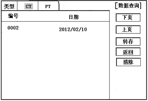
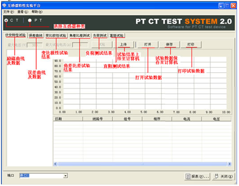
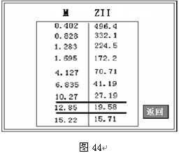
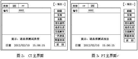
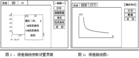
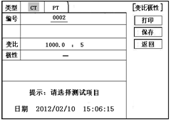
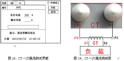
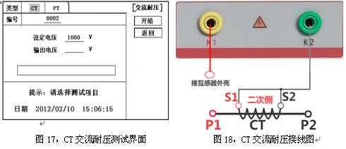
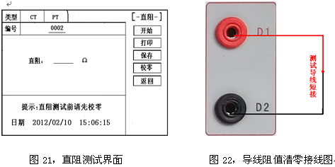
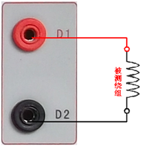
Transformer tester is very practical designed usage Designed for automatic testing of protective and metrology CT/PT, suitable for both laboratory and on-site inspections. Guideline GB 1207-2006, GB 1208-2006 Transformer tester is very practical Main features Supports detection of CT and PT Meet the GB1207, GB1208 and other regulatory requirements. No need to connect other auxiliary equipment, single machine can complete all inspection items. Comes with a miniature, fast printer that prints test results directly on site. Using an intelligent controller, the operation is simple. Large screen LCD, graphical display interface. Automatically give the CT/PT (excitation) inflection point according to the procedure. Automatically gives 5% and 10% error curves. Can save 3000 sets of test data, not lost after power off. Support U disk transfer data, can be read by standard PC and generate WORD report. Compact and lightweight ≤ 22Kg, very conducive to on-site testing. Transformer tester is very practical The main test function: (see Table 1) CT (protection, measurement) PT Volt-ampere characteristic (excitation characteristic) curve Volt-ampere characteristic (excitation characteristic) curve Automatically give the inflection point value Automatically give the inflection point value Automatically give 5% and 10% error curves Ratio measurement Ratio measurement Polarity judgment Ratio measurement Ratio measurement Angle difference measurement Angle difference measurement Polarity judgment AC withstand voltage test One pass test Secondary load test AC withstand voltage test Secondary winding test Secondary load test Iron core automatic demagnetization Secondary winding test Iron core automatic demagnetization           Table 1 Transformer tester is very practical The main technical parameters: (See Table 2) Items Parameters Working power AC220V±10%, 50Hz Device output 0 to 2500V (0-20A) Output current 0 to 600A (0-5V) Secondary winding Resistance measurement range 0~300Ω Accuracy 0.5%±1mΩ Secondary actual Load measurement range 0~300VA Accuracy ≤0.5% CT/PT Angle difference measurement Accuracy ±4min Resolution 0.1min CT/PT Ratio measurement Accuracy ≤0.05% Resolution 0.1 CT Ratio measurement range 1-50000 Accuracy ≤0.5% PT Ratio measurement range 1-10000 Accuracy ≤0.5% working environment Temperature: -10°C to 40°C, Humidity: ≤90%, Altitude: ≤1000m size 380mm × 240mm × 260mm weight ≤ 22Kg Table 2 5.1. Working conditions The tester should be powered by a power outlet with protective ground. If there is a problem with the connection to the protective ground, or if the power supply has no isolated connection to ground, the tester can still be used, but we do not guarantee safety; The parameter corresponds to an ambient temperature of 23°C ± 5°C; The guaranteed value is valid for one year after the factory calibration. Transformer tester is very practical Hardware structure 6.1. Panel structure: (Figure 1) figure 1 6.2. Panel notes: 1 —— Equipment ground terminal 2 - monitor logo 3 - Communication port 4 - Printer 5 - LCD display 6 - Controller 7 - High current output port when CT ratio/polarity test 8 - Secondary access port for CT ratio/polarity (angle difference/ratio difference) test 9 —— Voltage output port for CT/PT volt-ampere characteristic test; CT/PT load test port 10 —— Primary side access port when PT ratio/polarity (angle difference/ratio difference test) 11 ——Secondary access port when PT ratio/polarity (angle difference/ratio difference test) 12 —— CT/PT direct resistance test port 13 —— Overcurrent Protection (Power) Switch 14 —— Host Switch 15 —— Host Power Outlet 16,17,18,19,20,21, - wiring diagram of test items Transformer tester is very practical Operation method and main interface introduction 1, the use of the controller The controller has three operating states: "Left", "Right", "Press". These three operations using the controller can be conveniently used to move the cursor, enter data, and select items. 2, the main menu (see Figure 2) The main menu has "excitation", "load", "straight resistance", "polarity ratio", "corner ratio difference", "AC withstand voltage", "one-time flow", "data query", "return" 9 options can be selected and set using the controller. 8.CT test When performing the current transformer excitation characteristic, ratio, polarity, load, direct resistance, primary flow, angle difference, ratio difference, AC withstand voltage test, move the cursor to the CT and select the corresponding test option. CT excitation (volt-ampere) characteristic test In the CT main interface, after selecting the “excitation†option, the test interface is entered as shown in Figure 4. 1), parameter settings: Excitation current: The setting range (0-20A) is the highest setting current of the instrument output. If the current reaches the set value in the experiment, the current will be automatically stopped to prevent damage to the device. Usually the current setting value is greater than or equal to 1A, the inflection point value can be tested. Excitation voltage: The setting range (0-2500V) is the highest setting voltage of the instrument output. Usually the voltage setting value is slightly larger than the inflection point voltage. This can make the ratio of the curve display more consistent, the voltage setting is too high, the curve is close to the Y axis, and the voltage is set Low, the curve is close to the X axis. If the voltage reaches the set value in the experiment, the boost will be stopped automatically to avoid damage to the equipment. test: Wiring diagram see (Figure 5), the tester K1, K2 for the voltage output terminal, the test will be K1, K2, respectively, connected to the transformer S1, S2 (all terminals of the transformer should be disconnected). After checking that the wiring is correct, close the power switch and select the "Start" option, that is, start the test. During the test, the cursor is on the “stop†option, and it does not stop flashing. The tester starts to automatically boost and up-flow. When the tester is finished testing, the test is completed and the volt-ampere characteristic curve is drawn (see Figure 6). Note: In the interface of Fig. 4, the “Calibration†function is mainly used to detect the voltage and current values ​​of the instrument's own excitation characteristic test. See Appendix 1 for the detection method. 2), Volt-ampere characteristics (excitation) test result operation instructions After the test is completed, the screen shows the volt-ampere characteristic test curve (see Figure 6). Each operation function on this interface is as follows: Printing: After the controller selects “Printâ€, it will print the volt-ampere characteristics (excitation) curve and data one by one to facilitate the user to use for reporting. At the same time reduce the frequency of replacing paper, save time and improve efficiency. Excitation data: Move the cursor to the “excitation data†option, and the test data list of the volt-ampere (excitation) characteristic test will be displayed on the screen (see Figure 7). Press "back" to return to the volt-ampere characteristic test curve interface, and the controller can realize data up and down. When the page is flipped, you have reached the last page. Save: The controller moves to the “Save†option. Press to save the current measured data. After the save, the “Saved†is displayed on the screen. After successful saving, if the user presses the “save†key again, the program will automatically resolve and do not save the same test record. And can be viewed in the data query menu. Error curve: In the interface of Figure 6, after the cursor is moved to the “error curveâ€, the error curve of the volt-ampere characteristic test is displayed on the screen (see Figure 8). The error curve calculated after selection is shown in Figure 9. The following four items are the setting items for error curve calculation: ZII: CT secondary impedance. Rated current: CT's secondary side rated current 5% error curve: Automatically calculates 5% error curve data and displays the error curve. 10% error curve: Automatically calculate 10% error curve data and display error curve. There are three options in the error curve interface: Print : print out the error curve and data; Data: The error curve related data can be displayed, and the viewing mode is same as the volt-ampere characteristic data. Return : Return to the previous menu. Note: For each volt-ampere characteristic test, the tester automatically completes the demagnetization of the transformer. 1) Parameter settings: In the CT main interface, after selecting “Variable Polarity Ratioâ€, enter the test interface shown in Figure 10, and set the primary side test current: 0~600A, the maximum current output by the tester P1 and P2 terminals; Secondary side rated current: 1A or 5A. 2) Test: Refer to Figure 11 for wiring. CT is connected on one side to P1 and P2. CT is connected on the secondary side to S1 and S2. The undetected secondary winding is shorted. After setting the secondary side rated current and number, close the power switch and select " Start the option, press the controller and the test begins. During the test, the cursor keeps flashing on the “Test†option until the test is completed, the automatic test interface is exited, or the controller is pressed to artificially stop the test. After the device test is completed, the test is automatically stopped. After the test is completed, the polarity ratio is displayed. Test results (Figure 12). You can select the Save, Print, and Back options for the next step. The same color terminal of the instrument itself is the in-phase terminal, that is, P1 is connected to P1 of CT, and S1 is connected to S1 of CT. The polarity test result is a minus polarity. Figure 12, CT ratio polarity test results interface 3, CT angle difference ratio test 1) Parameter settings: In the CT main interface, select “Angle difference ratio†and enter the test interface (Figure 13). (Note: The actual rated change ratio on the transformer nameplate should be set.) CT rated current: 0~25000A, Secondary rated current: 5A/1A. Set transformer rated load and select "full load" or "light load" (light load is 25% of full load). 2) Test: The wiring is performed with reference to FIG. 11 , where the primary side of CT is connected to P1 and P2, and the secondary side of CT is connected to S1 and S2. After setting the parameters and checking that the wiring is correct, close the power switch, select the "Start" option, press the controller, and the test begins. During the test, the test can be terminated by pressing the controller. The phase angle difference between the primary and secondary sides is automatically calculated after the test is completed, and the percentage difference between the actually measured ratio and the rated change ratio set by the user is determined (Figure 14). You can select the Save, Print, and Back options for the next step. 4, CT flow test 1) Parameter settings: In the main interface of CT test, select to enter the "one-time through flow" test interface shown in Figure 15, set the current through current 0 ~ 600A. 2) Test: Refer to Figure 16 for wiring. CT is connected on one side to P1 and P2, and CT is connected on the secondary side to the secondary load. After setting the flow current, close the power switch, rotate the controller to move the cursor to the “start†option, press the controller, the test starts, and the current holding time is displayed on the progress bar (0~200A: hold for 10 minutes; 201A ~500A: Hold for 2 minutes; >500A: Hold for 3 seconds). Transformer tester is very practical CT AC withstand voltage test 1, the parameter settings: In the main interface of CT test, select to enter the "AC withstand voltage" test interface (Figure 17), the user can set the AC output voltage 0 ~ 2000V according to need. 2, experiment: Refer to Figure 18 for wiring. The secondary side of the tested CT is short-circuited to the voltage output port K2 of the tester, and the other end of the voltage output port K1 is connected to the transformer shell. Check the wiring is completed, close the power switch, select the "start" option, press the start to boost, the voltage holding time defaults to 1 minute, the test process, the instrument internal leakage current between the transformer secondary winding and the shell Real-time detection, if you find that the current increases rapidly, it will automatically return to zero and the page will show a test abnormality. Transformer tester is very practical CT load test parameter settings: In the main interface of CT test, select to enter the "Load" test interface (Figure 19), set the secondary side rated current: 1A or 5A. test: The K1 and K2 of the tester are the voltage output terminals. Refer to Figure 20 for wiring. Connect the measured load (load) to the K1 and K2 terminals of the tester. After checking the wiring is correct, close the power switch and select “Start†to start the test. After the test is completed, the load test result is displayed. You can select the "Save", "Print" and "Return" options for the next operation. 7. Direct resistance test: 1), school zero: In the main interface of CT test, select to enter the “straight resistance†test interface (see Figure 21). Before the test, zero the test lead, and select the direct resistance test item on the CT main interface display menu. Direct resistance test interface (Figure 11) and select “zero calibrationâ€. Connect the clamps of the test leads before the zero calibration (short-circuit the test leads) (Figure 22), and then perform zero calibration. After the calibration is completed, the interface prompts “School Zero finished." 2) Test: After the zero calibration is over, connect the test line with reference to Figure 23. Tester's D1 and D2 are connected to the measured winding. Select the "Start" button to start the test. After the test is completed, the direct resistance test result will be displayed. You can select "Save". "Print" and "Back" options for the next step. Figure 23, direct resistance test wiring diagram 9.PT test When performing the voltage transformer excitation characteristic, ratio, polarity, load, direct resistance, angle difference, ratio difference, AC withstand voltage test, move the cursor to the PT and select the corresponding test option. 1), parameter settings Press “Excitation†button, enter the test interface as shown in Figure 24. Excitation current (0~20A): The output current is the highest setting current of the instrument output. If the current reaches the set value in the test, it will stop the current up automatically. Usually 1A can test the inflection point value. Excitation voltage: According to the rated secondary settings: 100V, 100/√3, 100/3, 150V, 220V. 2) Test: Referring to Figure 25 wiring, the tester is the voltage output terminal. When testing, connect K1 and K2 to the a and x of the transformer, and the zero terminal of the primary winding of the voltage transformer should be grounded. After checking the wiring is correct, close the power switch and select the “Start†option to start the test. During the test, the cursor stays on the “stop†option and does not stop blinking. The tester starts to automatically boost and up-flow. After the tester is finished testing, the test is completed and the volt-ampere characteristic curve is drawn. 3), PT (excitation) test results operation instructions Please refer to the 8 page CT test results 2, PT change ratio polarity test 1) Parameter settings: In the main interface of the PT test, select to enter the “Variable Polarity†test interface (Figure 26) and set the rated secondary voltage: 100V, 100/√3, 100/3, 150V, 220V 2) Start the test: Referring to Figure 27 for wiring, PT is connected to A and X on one side and PT is connected to a and x on the secondary side. After setting the secondary side rated pressure and number, close the power switch, select the "Start" option, press the controller, and the test begins. During the test, the cursor keeps flashing on the “Test†option until the test is completed, the automatic test interface is exited, or the controller is pressed to artificially stop the test. After the test is completed, the polarity ratio test result is displayed (Figure 28). You can select the Save, Print, and Back options for the next step. The same color terminal of the instrument itself is the in-phase terminal, that is, A is connected to PT A, and when X is connected to PT X, the polarity test result is minus polarity. Figure 28, PT Ratio Polarity Test Results Interface 3, PT angle difference ratio test 1) Parameter settings: In the PT test main interface, select to enter the “angle difference ratio†test interface (see Figure 29), refer to the rated transformation ratio on the transformer nameplate, set a primary rated voltage of PT 0-500KV, secondary rated voltage, Rated load, and full load or light load test. (light load is 25% of full load). 2) Test: Referring to Figure 27 for wiring, PT is connected to A and X on one side and CT is connected to a and x on the secondary side. After setting the parameters, rotate the controller to move the cursor to the Start option, press the controller, and the test begins. During the test, the test can be terminated by pressing the controller. After the test is completed, the phase angle difference between the primary and secondary sides is automatically calculated. The actual measured ratio is different from the percentage set by the user (Figure 30). Press Print to print out the test results, save to save the test results, and return to return to the parameter settings menu. If the display is all 9, the error is out of the display range. Please check the setting value. 4, PT AC withstand voltage test 1, the parameter settings: In the PT test main interface, select to enter the "AC withstand voltage" test interface (Figure 31), the user can set the AC output voltage 0 ~ 2000V. 2, experiment: Referring to Figure 32, the secondary side of the tested PT is short-circuited to the voltage output port K2 of the tester, and the other end of the voltage output port K1 is connected to the transformer shell. Check the wiring is completed, close the power switch, select the "start" option, press the start to boost, the voltage retention time defaults to 1 minute, the test process, the instrument internal leakage current between the transformer secondary winding and the shell Real-time detection, if you find that the current increases rapidly, it will automatically return to zero and the page will show a test abnormality. Transformer tester is very practical PT load test 1, the parameter settings: In the PT test main interface, select to enter the "load" test interface (Figure 33), set the rated secondary voltage value: 100V, 100/√3, 100/3. 2, test: The K1 and K2 of the tester are the voltage output terminals. Refer to Figure 34 for wiring. Connect the measured load (load) to the K1 and K2 terminals of the tester. After checking that the wiring is correct, close the power switch and select "Start" to start the test. After the test is completed, the load test result is displayed. You can select the "Save", "Print" and "Return" options for the next operation. 6, straight resistance test: 1), school zero: In the main interface of the PT test, select to enter the “straight resistance†test interface (see Figure 35). Before the test, zero the test lead, and select the direct resistance test item on the PT main interface display menu. Direct resistance test interface and select “zero calibrationâ€. Connect the clamps of the test leads before the zero calibration (short-circuit the test leads) (Figure 36), and then perform zero calibration. After the calibration is completed, the interface will prompt “zero completionâ€. 2) Test: After the zero calibration is over, connect the test line with reference to Figure 37. Connect the D1 and D2 of the tester to the measured winding. Select the “Start†button to start the test. After the test is completed, the direct resistance test result will be displayed. You can select “Saveâ€. "Print" and "Back" options for the next step. Figure 37, direct resistance test wiring diagram 10. Data query In the main interface of CT/PT test, select to enter the "Data Query" test interface (Figure 38), select "excitation", "load", "straight resistance", "change ratio polarity", and "angle difference ratio" as required Test options such as “badâ€, “returnâ€, etc., after selecting the test item, enter the test interface of Figure 39. The latest test results saved under this item in the instrument can be displayed. You can select “upâ€, “downâ€, “turn†Save, Return, Clear options to operate accordingly. When transferring, plug in the U disk to the tester communication port “USBâ€. In Figure 39, click “Dump†to transfer the test record displayed under the current page to the U disk. The time taken for each record is about 2 seconds. After the transfer is completed, the interface prompts "Dumping completed". Figure 39 11. Instructions for use of PC operating software (Figure 40) 11.1. Insert the CD-ROM into the CD-ROM drive of the computer, unzip the “software†to the root directory of drive C, open the Execute folder, and select “Dqsy†file, which is the transformer test software. 11.2. Connect the U disk that stores the test data to the computer. 11.3. Open the "Dqsy" software (take CT as an example) and select the transformer type "CT" or "PT". 11.4. Select “Uploadâ€, then upload the test data to the computer, upload four sets of test data each time, continue to select “Uploadâ€, and select another four sets of test data. At the end of uploading, you can select options such as "Volt-ampere characteristic test", "Error curve", "Variable polarity test", "Angle difference ratio test", "Load test", and "Direct resistance test". 11.5. Select the “Save†option to save the corresponding test data in “HTML†format, which can be viewed with the IE browser. It is very convenient. 11.6. Select the "Print" option to display the results in the form of a report for easy printing. 11.7, PT excitation characteristic test results, please refer to the above CT operation. Figure 40 Attached Appendix I. "Calibration" Test Method (CT as an example) 1) Parameter settings: After entering the CT "excitation" test interface, select to enter the "calibration" test interface (Figure 41), set the excitation current value: 0.1A ~ 5A; excitation voltage value: 1V ~ 1000V. 2) Start: Voltage calibration test refers to Figure 42 for wiring; set the measured voltage, close the power switch, select the "Start" option, press the controller, the test is started, the test will reach the set value will maintain the output voltage / current value After testing, after testing, press the controller and the test returns to the interface in Figure 41. The current calibration test is performed with reference to Figure 43. The voltage setting is slightly higher than [Current setting (A) * Load (Ω)]. After setting the measured current/voltage value, close the power switch and select "Start". Option, press the controller, the test is started, after the test reaches the set value will maintain the output current / voltage value for testing, after the test is completed, press the controller, the test returns to Figure 41 interface. Appendix II, after-sales service commitments, this product warranty for one year, life-long maintenance. Appendix III, Error Curve Description According to the data of the 5% and 10% error curve between the current multiple (M) and the allowable secondary load (ZII) calculated from the excitation current and voltage of the transformer secondary side, the transformer protection winding can also be judged as qualified: 1) The actual load measured near the theoretical current multiple is greater than the theoretical load value on the transformer nameplate, indicating that the transformer is qualified as shown in Figure 44; 2) The actual current multiple measured near the theoretical load is greater than the theoretical current multiple on the transformer nameplate, which also shows that the transformer is qualified as shown in Figure 44; The secondary load of the protective current transformer should meet the requirements of the 5% error curve, as long as the secondary actual load of the current transformer is less than the allowable load of the 5% error curve. Under the rated current multiple, the measurement error of the qualified current transformer is Less than 5%. The greater the secondary load, the easier the current transformer core is saturated and the smaller the allowable current multiple is. Therefore, the 5% error curve, the n/ZL curve, is the curve shown in Figure 9. In the example shown in Fig. 44 (5P10 20VA for the tested CT): 5 is the accuracy level (error limit is 5%), P is the transformer type (protection level), and 10 is the accurate limit factor (10 times) Rated current), 20VA indicates rated secondary load (capacity). When the current multiple is 10.27 times (nearly 10 times), the allowable secondary load is 27.19 ohms, which is larger than the rated load 20 VA (20VA/1=20 ohms) of this CT. Through this data, it can be judged that the transformer is qualified. In addition, the allowable secondary load at the secondary load of 19.58 Ω (close to 20 Ω) is 27.19 Ω, which is larger than the rated load of the CT 20 VA (20 VA/1=20 Ω). This data can be used to judge that the transformer is qualified. In addition, when the secondary load is 19.58 Ω (close to 20 Ω), the allowable current multiple is 12.85 times, which is larger than the rated current multiple of the CT (10 times), and the transformer can be judged as passing through this data. In fact, as long as one of these two key points is found, it can be determined whether the measured transformer is qualified or not. If the 10% error does not meet the requirements, the general practice is: Increase the secondary cable boundary area (decrease the secondary impedance) Connected in the same type with the same ratio current transformer (reduce the transformer excitation current) Change to a higher volt-ampere characteristic winding (increased excitation impedance) Increase the current transformer ratio (increase the excitation impedance) Error curve formula: M = (I*P)/N ZII = (U-(I*Z2))/(K*I) I current U voltage N=1 (1A rated current) I current N=5 (5A rated current) Z2 CT secondary impedance P=20 (5% error curve) K=19 (5% error curve. 1A 5A rated current) P=10 (10% error curve) K=9 (10% error curve. 1A 5A rated current) Several models of trimmers are available for trimming different kinds of brushes. They can be used to trim round brushes like toilet brushes, bottle wash brushes, dishwashing brushes or other spherical or semi-spherical brushes, or to trim hair brushes (curved or flat brushes), and to trim toothbrushes or similar small brushes. Brush Trimmer, Brush Trimming, Brush Trimming Device, Brush Trimming Equipment, Brush Trimming Tool Yangzhou Haixing CNC Brush Machine Co., Ltd. , https://www.brushmachine.com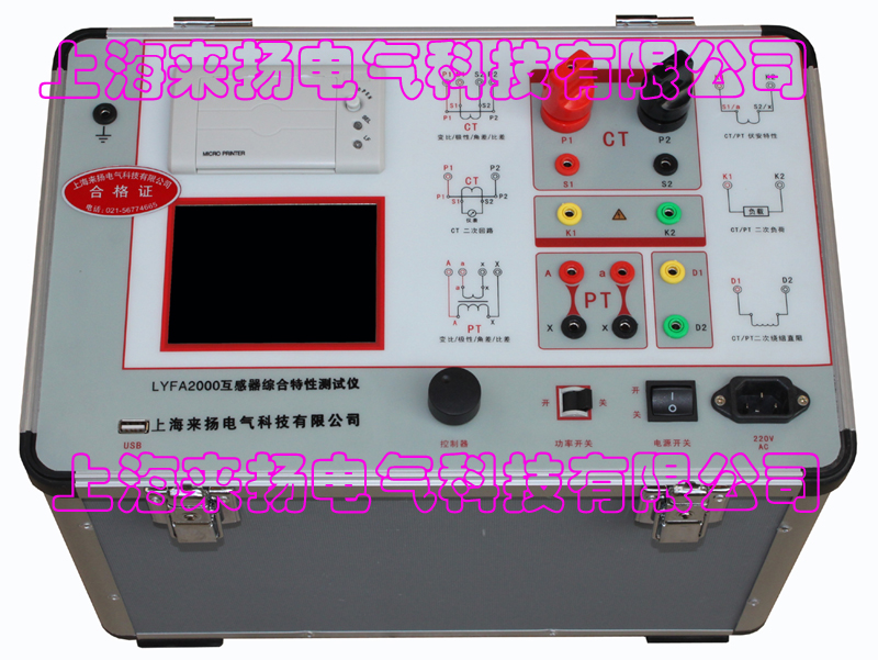
 Input voltage 220Vac±10%, rated frequency 50Hz;

 2. CT ratio polarity test
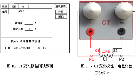


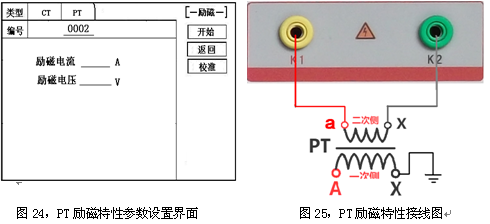
 1, PT excitation characteristic test